September 29, 2017
Of course, doing a static code-analysis can’t in any way tell you that you are doing DDD correctly. But what it can do, is to help you to meet some basic principles like a clean aggregate structure and keep them intact over time. The implementation details of Domain Driven Design that I have taken a look on for my analysis are mostly based on common literature, in particular “Domain-driven Design” by Eric Evans and “Implementing Domain-driven Design” by Vaughn Vernon. Additionally, I got support and good ideas from the guys at Smartsquare, where I wrote the thesis and developed the analysis.
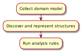
As only IDDD alone is over 600 pages, I had to boil everything down to a set of core principles. Those had to be applied to a software project without actual knowledge of the domain and still return meaningful results, based only on source code. In the end I settled with 10 rules, that I was going to implement. As all of those rules at least need to know which classes represent which parts (Entity, Value Object, Repository,…) in the domain model or are even part of it, there is some configuration needed to collect those model parts as a first step (see figure 1). In the second step the domain models internal structures are discovered and represented in a way, that analysis rules can easily access them. In the final third step the actual analysis rules are executed, based of the results of the other steps.
Step 1: Collecting the domain model
Without a correct knowledge of the individual parts of the domain model and their designated roles, the later steps couldn’t possibly come to any meaningful results, so it’s quite important to get this right. To avoid the need for significant changes in the code base, the collection can work in three different ways:
- Using the class hierarchy should be the favored way, as it allows to place additional constraints on your domain model. For example the use of F-bounded Polymorphism to check your aggregate structure at compile time.
- Using name patterns makes sense if your classes are named in a way that allows to reliably identify their parts in the domain model. A good example are repositories that are often named
EntityNameRepository, so everything that matches the RegEx.*Repository$could be interpreted as a repository. - Using annotations is the preferred way if no class hierarchy or name pattern is available. In some cases it might work to use existing annotations like those from a persistence framework. If those should be used, make sure that, for example
@Entityand@Embeddableexactly match to entities and value objects.
To guarantee maximum flexibility, all three methods can be used simultaneously or side by side. To minimize the amount of false-positive collected classes, a model package can be set and only classes in that will be used for the first analysis step. Otherwise collecting classes based on class hierarchy would lead to implementations of repositories and infrastructure services incorrectly being treated as part of the domain model.
Step 2: Discovering internal structures
After all parts of the domain model have been collected, there’s not yet any connection between those individual parts. Some analysis rules could theoretically be run on the individual parts, but other need knowledge about the internal structures of the domain model. Currently only the aggregate structure is discovered in this step, but in later versions other structures and relationships might be added as well. For example the entity-repository associations to analyze if all repositories belong to an aggregate root.
The aggregate structure is mapped to a directed graph where all entities and value objects represent nodes and their relations are inserted as edges. This allows the analysis rules for aggregate structure to be implemented as graph traversals. To be able to represent not only valid but also invalid aggregate structures, all aggregates are put into a single (but not necessarily connected) graph. Also, value objects are being treated as equal to entities, as otherwise big aggregates containing value objects that then hold other entities wouldn’t be treated correctly. On an abstract level, this is a good example that in this special case data structures and algorithms must not only work for correct, but especially for incorrect structures to allow them being analyzed and reported.
Step 3: The analysis rules
Now that all data is collected, it’s time to get to the actual analysis rules. I’ve listed them each with their motivation and expected outcomes:
- Each entity type has an identity
that is accessible by a method that follows a set name pattern. This is one of the most basic rules and no issues were expected. - Immutability of value objects
should be given, so that there are no setter methods and all properties should be declared as final. Also one of the more basic rules, some issues expected especially non final properties. - Signs of an anemic domain model
should not be found. Checks if there are entities which only consist of getters and setters, which is an obvious sign of anemic behavior. - A correct aggregate structure
should be kept, so that single aggregates resemble a tree structure and link to each other only by their identities. As this is a higher level rule, there were some issues expected to be found. - A maximum size per aggregate
should not be exceeded to reduce transaction failures and read less unneeded data from persistence. As for aggregate structure, some issues are expected. Especially, as a general upper limit is hardly quantifiable and can change from domain to domain. The upper limit of entities per aggregate can be set individually for a project. - Usage of domain services
should be restricted only in cases where functionality can’t be put into an entity, so every domain service (in contrast to an infrastructure service) should work on at least two different types of entities. - Implementation of repositories
should be done outside the actual domain model, only a persistence independent interface should be part of it. As this is again a very basic rule and also used outside of DDD projects, no issues are expected. - Dependencies of the domain model
to other parts of the application should not be present. The domain model should be encapsulated and only depend on library functionality. This is again a relatively high level rule, so issues might be expected, but less than for incorrect or too big aggregates.
This list does in no way claim to be complete, those are just the rules I was able to identify and implement during the time of my master thesis. If you want to try the SonarQube plug-in yourself, take a look at the Github repository mrm1st3r/sonar-ddd-plugin. It does rely on some internal parts of the SonarJava plug-in, so I can’t guarantee that it currently works on other versions than 4.8.
To keep the size of this article reasonable, I decided to split it into three parts, beginning with this one. Part 2 will cover the implementation details of the SonarQube plug-in itself and part 3 will show the results of a sample analysis of some open source projects.